RCB Networking Setup
Connecting I/O Lines
The I/O lines can drive up to 8mA of current. The following is the mapping between I/O pins:
| RCB Name | Description |
|---|---|
| PA0 | Price Low |
| PA1 | Price Med |
| PA2 | Price High |
| PA3 | Price Critical |
| PA4 | Price going up in 2 hours |
| PA5 | Price going down in 2 hours |
| PA6 | Price going up in Tprog hours |
| PD4 | Price going down in Tprog hours |
| GND | Ground. Reference for the I/O lines, and also used as the negative for the supply voltage. |
| VCC | +3.3V supply voltage. If the battery pack is used do not connect this line! |
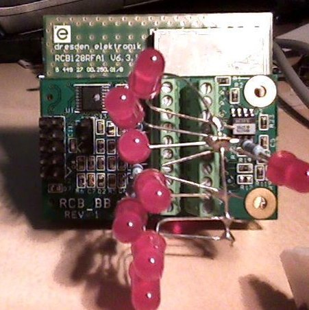
All I/O lines are active high. To test the lines, connect a LED (ideally 3mm) in series with a 1K resistor to ground. The following shows an example of this connection:
Connecting Serial Port
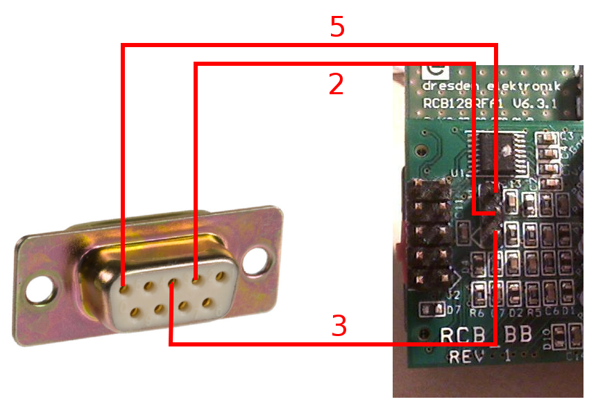
The serial port is connected to the three-pin header on the RCB-BB. Any sort of 3-pin female connector can be used, a DB-9 is needed on the other side to plug into the computer.
The pinout is as follows:
| RCB-BB Pin | DB-9 Female |
|---|---|
| 1 | 3 |
| 2 | 2 |
| 3 | 5 |
The communication to the host computer is done using a straight-through serial cable. Open a terminal emulator on the com port, use the following settings:
| Baud Rate | 38400 |
|---|---|
| Data Bits | 8 |
| Flow Control | None |
| Stop Bits | 1 |
Note if you are only asked for the baud rate the default settings should be fine for the rest of the stuff (data bits, flow, and stop).
Programming
Programming is done through the JTAG connector. The JTAG connector fits as follows:
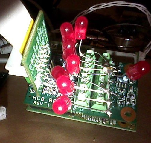
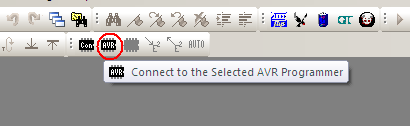
To use the JTAG install AVR Studio. Plug the JTAG in, some drivers will probably install. Next with the RCB connected and powered on, press the program button:
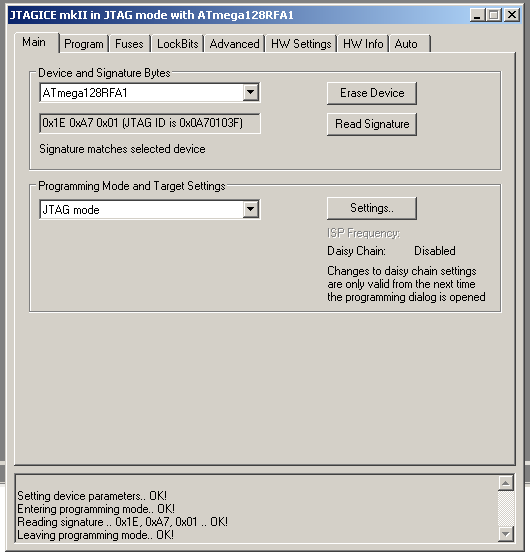
Then select the AtMega128RFA1 device, and hit ‘read signature’ to verify it is connected correctly:
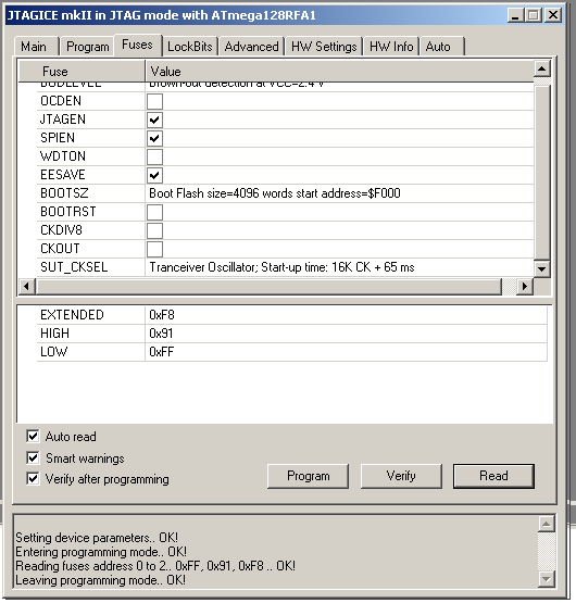
Go to the ‘fuses’ tab, and hit ‘read’. Verify the fuses look like the following image, if not change them and hit ‘program’. You will only need to do this once for each device, the fuses are saved separately from FLASH memory:
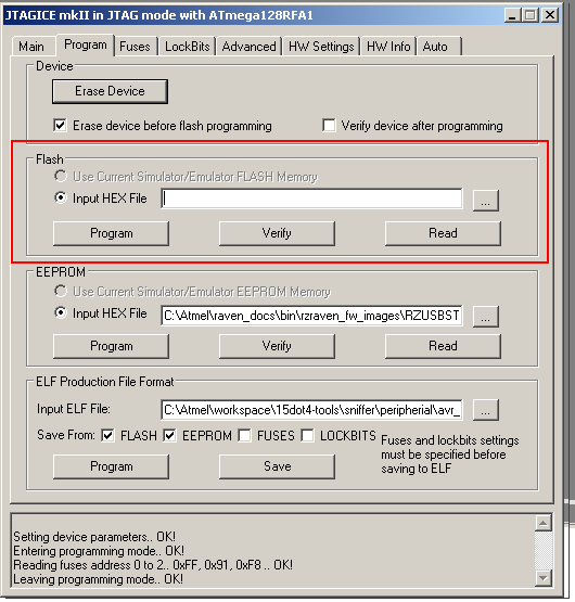
Finally using the FLASH programming option, select the .hex file and program it in with ‘Program’. Check the status in the little status window at the bottom of the dialog box:
Programming Files
| File | Date | Description |
|---|---|---|
| 02JUNE2010_1516.hex | June 6, 2010. 15:16 | Incomplete example, lights up LEDs and has serial port |
| 14JUN2010_2045.hex | June 14, 2010. 20:45 | First test for BOSCH |
| 15JUN2010_1209.hex | June 15, 2010. 12:09 | Add tProg command, store tProg and poll in EEPROM |
Initial Setup
Connect to the serial port. On the device to be the meter, run the following (ignore any error messages coming through): ^ smc e ^ Then power cycle the device. On the devices to be end-nodes, run the following: ^ smr e ^ Then power cycle the device.
Responses / Meter Commands
Restrictions / Changes
- Formats have been changed to reduce length.
- Only one tariff profile is supported, /pr/0
- Multiple tariff’s are supported within that tariff profile though
- The ‘active’ tariff is changed to a link
GET /tm/0
HTTP/1.1 200 OK
Content-Type: application/exi

<?xml version=’1.0’ encoding=’UTF-8’?>
<Time xmlns=’http{s}://ref/ver’>
  <UnixTm>123456789</UnixTm>
</Time>
GET /pr/0/tff
HTTP/1.1 200 OK
Content-Type: application/exi

<?xml version=’1.0’ encoding=’UTF-8’?>
<TariffProfile xmlns=’http{s}://ref/ver’>
  <TTI href="/pr/0/tff/0" />
  <TTI href="/pr/0/tff/1" />
</TariffProfile >
GET /pr/0/tff/0
HTTP/1.1 200 OK
Content-Type: application/exi

<?xml version=’1.0’ encoding=’UTF-8’?>
<TTI xmlns=’http{s}://ref/ver’>
  <startTime>00:00:01</startTime>
  <endTime>08:00:00</endTime>
  <Charge>
    <fixed>
      <val>0.04</val>
      <cur>USD</cur>
    </fixed>
  </Charge>
</TTI>
GET /pr/0/tff/act
HTTP/1.1 200 OK
Content-Type: application/exi

<?xml version=’1.0’ encoding=’UTF-8’?>
<ActiveTariff xmlns=’http{s}://ref/ver’>
  <TTI href="/pr/0/tff/0" />
</ActiveTariff>