Al-Bot
[A Quick Note]
First off, this did use to be called STANN Robot. The name changed when I was working on it though to
Al-bot, thats is AL-bot and not AI-bot. The reason for this is my friends young cousins mis-pronounced
AI-bot (for Artificial Intelligence bot) as ‘Al-bot’ in a game, and the name stuck.
**[A Huge Thanks]**This project has really been intersting so far, and I have learned a lot from it. However there have been a few people I would like to thank greatly, they are:
Atmel - Provided me with STK500, STK501, JTAG
ICE and some AtMega128 samples. These development
tools have been a key part in the design
of my robot, and make it possible to do much
more in less time!
Eivind Sivertsen - Webmaster of AVRFreaks.net
Jacob Lunn Lassen - Field Application Engineer for Atmel AVR
Products in Norway
Tim Kitagawa - Atmel Field Application Engineer in Canada
Joe Young - Regional Sales Manager for Atmel in Canada
Honeywell - Provided me with M22S rotation sensor
Yan Gaudet - Technical Application Specialist
[Results]
This project was my entry into the local
science fair (April 2nd to 5th 2003) where
I won the following awards:
Best in Fair - 2nd Place
Intel International Science and Engineering
Fair Trip
Gold Merit Award
Procor Senior
PEO (Professional Engineers of Ontario) Hamilton
Chapter - First Place
Mechanical Construction Association
McMaster University Tuition - Engineering
or Science
IISEF - Yale Science & Engineering
Dofasco - Process Automation
Bell Computer & Communications - 2nd
See http://basef.mcmaster.ca/2003/results/gallery/display_project.cgi?project_id=MA11 for more detail on my project there (has picture).
At the Intel International Science and Engineering Fair in Cleveland (May 2003) I won a third place award for the catagory of engineering and I attened this fair as a member of Team Canada 2003.
[Files]
You can download all my files (including
a large final report) here. If you do not have a username for AVRFreaks use ‘guest’ as username and ‘guestuser’ as password (no ’’ in names though).
[Works in Progess]
The following stuff is a bit random, and was uploaded as I worked on the project:
UPLOADED APRIL 10, 2003
The local science fair was recently (April 2 to 5), and I was awarded the following prizes at it for my project:
Best in Fair - 2nd Place
Intel International Science and Engineering
Fair Trip
Gold Merit Award
Procor Senior
PEO (Professional Engineers of Ontario) Hamilton
Chapter - First Place
Mechanical Construction Association
McMaster University Tuition - Engineering
or Science
IISEF - Yale Science & Engineering
Dofasco - Process Automation
Bell Computer & Communications - 2nd
See http://basef.mcmaster.ca/2003/results/gallery/display_project.cgi?project_id=MA11 for more detail on my project there (has picture). I will be going to the IISEF (Intel International Science and Engineering Fair) as well. Thanks again to all who have helped me out so far!
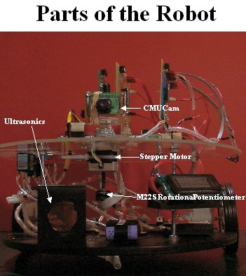
Here are two photos that were on by backboard
of the display, the show photos of the completed
robots as well as parts: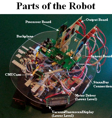
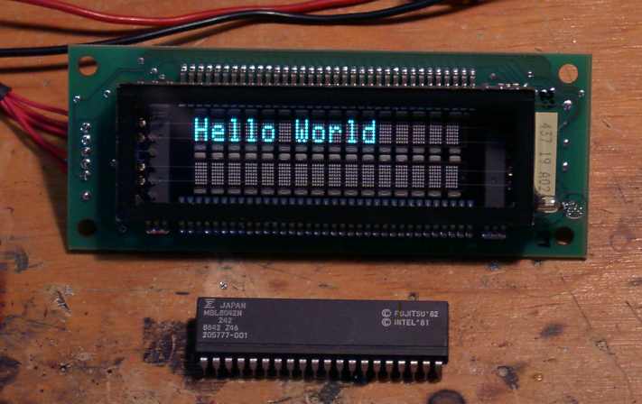
The Vacuum Flourescent Display on the bot
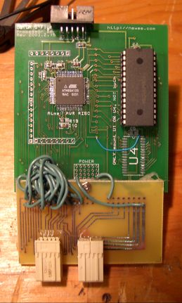
Another picture of the processor board. Note that I reversed one of the connectors, hence the adapter board glued on that corrects that error…
UPLOADED FEB 26, 2003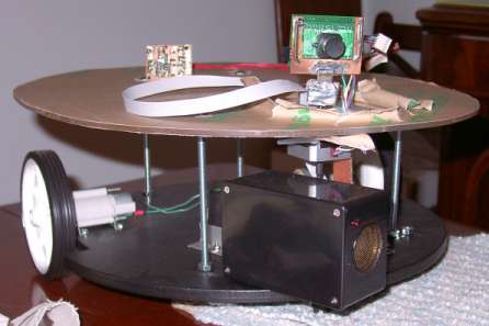
An updated image of the robot base. You can
see a few parts mounted. As well the top
of it is Lexan, but the protective paper
is still on it.
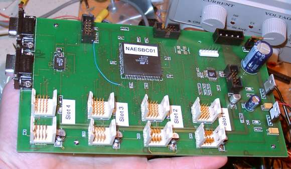
An updated picture of the finished backplane.
Here you can see everything mounted on it,
as well as a blue wire that corrects an error
in the PCB…
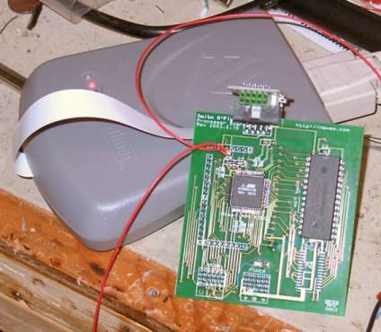
My processor board hooked up to my JTAG ICE.
The square chip is an AtMega128. The large
28-DIP is my FRAM chip. At the bottom you
can see a space for two connectors that plug
into the backplane. But I forgot to order
them from DigiKey so time for a new shipment…
The JTAG ICE is really helpful here, I could quickly test that my FRAM was working without having to get my serial port working and finding an RS232 line… plus the fact I had to use most of the port-pins in the AtMega128 here anyway made it hard to attach a LCD display to spare lines or whatnot.
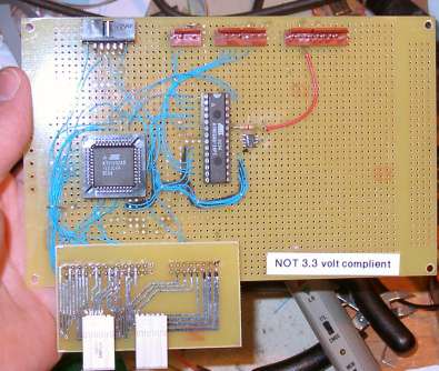
The ‘sensor board’. This thing connects to
the camera, the stepper motor, and the sonar.
Beside the AtMega8 (the 28-pin DIP) there
is a SMD op-amp mounted dead bug style.
The ’not 3.3 volt complient’ stickers are there because the ‘Stann Bus’ (the bus that is on the backplane) should be able to work at 3.3 OR 5 volts. This card doesn’t sense that though, and would rip apart a 3.3 volt bus by applying 5 volts on it. Actually none of the cards really work at 3.3 volts, but they DO recognize a 3.3 volt bus and just shut down to prevent them from breaking other cards… I guess since I DID make the protocol I could just take the 3.3 volt part out but oh well…
UPLOADED JAN 20, 2003
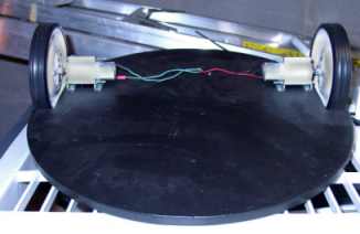
This is the base the robot will be built
on, at least one more level will be added.
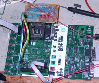
My STK500 + STK501 testing the FRAM interface
that will hold the neural network data
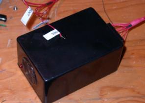
The SONAR module that will allow the robot
to detect obsticals
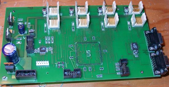
The backplane to which the other boards will
plug into. U5 is not yet mounted on it as
you can see…
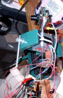
The CMUcam + motor + M22S sensor that track
on object. The camera can now track a ball
and is fairly intelligent, for example if
the ball goes out of range the camera will
continue to move in the last known direction
of ball movement to have a better chance
of “catching up”.
last updated Feb 27, 2003